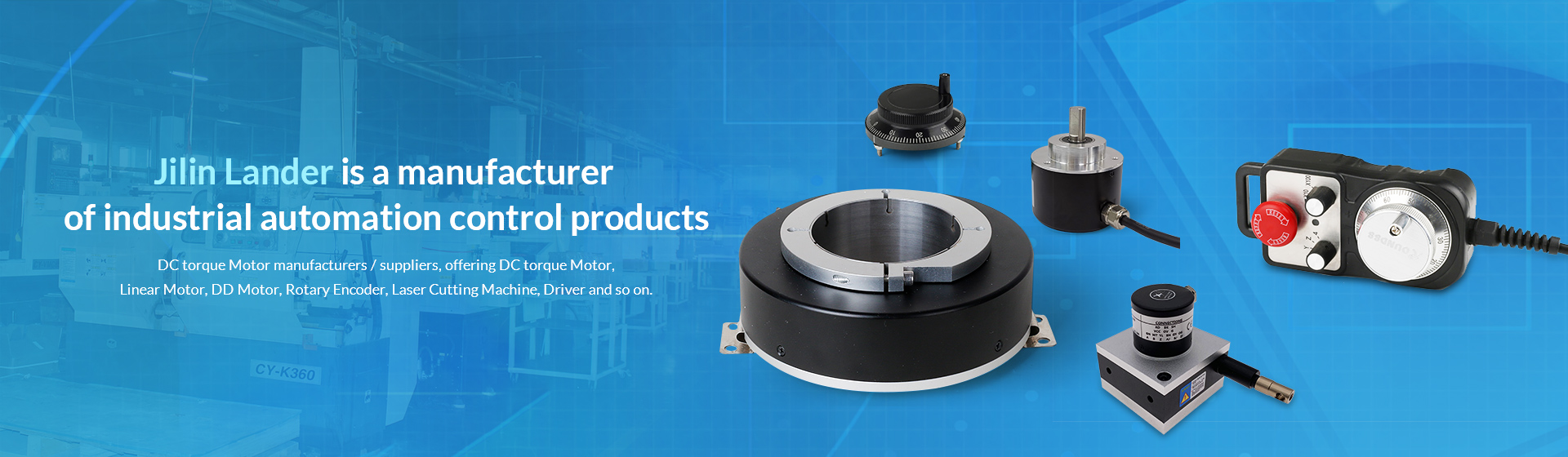
Where is the linear motor-driven electric washing machine?
Today's electric drying racks are usually driven by linear motors, while the previous electric drying racks used ordinary rotating electric machines. Why? Where is the linear motor driven transmission? let's see it together.
(1) The linear motor-driven transmission does not require any conversion device to directly generate thrust. Therefore, it can eliminate the intermediate conversion mechanism, simplify the entire device or system, ensure operational reliability, improve transmission efficiency, and reduce manufacturing. Cost and easy to maintain. According to foreign data reports, there was a washing machine with a linear motor that worked continuously for 24 hours every day for 24 hours without any maintenance.
(2) The ordinary rotating electric machine is limited by the centrifugal force, and its peripheral speed is limited. When the linear motor is running, its components and transmissions are not subjected to centrifugal force like the rotating electric machine, so its linear speed can be avoided. limit.
(3) The linear motor directly generates linear electromagnetic thrust through electric energy. In the driving device, it can move without mechanical contact, so that the transmission parts are not worn, thereby greatly reducing the mechanical loss, such as a linear motor driven maglev train. That's it.
(4) The rotating electric machine converts the rotary motion into a linear motion through a conversion mechanism such as a steel rope, a rack, a belt, etc., in the operation of the conversion mechanism, the noise is unavoidable, and the linear motor is operated by the electromagnetic thrust driving device. Therefore, the entire device or system has little or no noise and a good operating environment.
(5) Because the linear motor has a simple structure, and its primary core can be sealed with epoxy resin or the like after being embedded, it can be applied in some special occasions, for example, it can be used in wet or even water; it can be corrosive. It can be used in gas or toxic or harmful gases, and can be used at high temperatures of several thousand degrees or low temperatures of several hundred degrees.
2024-01-22
Application of linear motor on high speed machine tools
With the development of direct drive technology, the comparison between the linear motor and the traditional "rotary servo motor ball screw" drive mode has attracted industry attention. Now some of the world's most advanced machining center manufacturers are beginning to apply on their high-speed machine tools.
In terms of accuracy, the linear motor has a simple reduction of the interpolation hysteresis due to the transmission mechanism. The positioning accuracy, the reproduction accuracy, and the absolute accuracy are higher than the "rotary servo motor ball screw" by the position detection feedback control, and are easy to implement. Linear motor positioning accuracy can reach 0.1μm. "Rotary servo motor ball screw" up to 2~5μm, and requires CNC-servo motor-no-gap coupling-thrust bearing-cooling system-high-precision rolling guide-nut seat - Workbench closed-loop The transmission part of the whole system should be lighter and the grating accuracy should be high. If you want to achieve high stability, the "rotary servo motor ball screw" should be driven by two-axis. The linear motor is a high-heating component, and it needs to adopt strong cooling measures. To achieve the same purpose, the linear motor has to pay a higher price.
In terms of speed, the linear motor has considerable advantages. The linear motor speed reaches 300m/min and the acceleration reaches 10g. The ball screw speed is 120m/min and the acceleration is 1.5g. From the comparison of speed and acceleration, the linear motor has considerable The advantage, and the linear motor will further improve the speed after successfully solving the heating problem, and the "rotary servo motor ball screw" is limited in speed and it is difficult to improve more.
In terms of life, the linear motor has a mounting gap between the moving part and the fixed part, has no contact, and is not worn by the high-speed reciprocating motion of the mover. The long-term use has no change in the positioning accuracy of the motion, and is suitable for high-precision occasions. The ball screw can not guarantee the accuracy in high-speed reciprocating motion. Because of high-speed friction, the screw nut will wear and affect the accuracy of the motion. The demand for high precision cannot be met.
2024-01-10
Sun Sheng Computer Embroidery Machine Co., Ltd. is located in the Sewing Machine Accessories Center of Zhejiang Province, China, and is the largest sewing machine accessories trading center in Asia. Since its establishment in 2000, we have been striving to find high-quality and reasonably priced components that enable us to occupy a place in the fiercely competitive market. Now we have our own manufacturing factory that can produce a large number of high-quality parts to meet the requirements of all customers, and can supply:
Tagima, Barudan, Chinese brand computer embroidery machine accessories;
Spare parts for Sequin embroidery machine;
Spare parts for towels and special embroidery machines;
Spare parts for Schiffli machines;
Electrical spare parts;
Embroidery accessories and tools.
For more information, please visit our website.
If you are interested, please feel free to contact us at any time.
2024-01-09
Magnetic encoders are used in imaging systems such as X-ray, CT, PET, and MRI devices to replace analog potentiometers. MagRes encoders are available in single-turn and multi-turn versions, with standard 42- and 58-mm housings respectively. They have an optimum operating temperature of -20 to 85 degrees Celsius. The single-turn encoder weighs 120 grams and has a 12-bit resolution. The multi-turn encoder weighs 400 grams and has a 30-bit resolution. The device's zero-point adjustment is accompanied by a fan-shaped scan display and parallel output.
Source of information: pack.cn
2024-01-03
In the information technology era, security products have attracted more and more attention. In network monitoring systems, encoders are the bridge between monitoring storage and transmission. Rotary encoder is a common encoder, commonly used in monitoring video transmission equipment, speed measuring generators and other security products, used to measure the speed and with the PWM technology can achieve fast speed device, photoelectric rotary encoder through photoelectric conversion The output shaft angular displacement, angular velocity and other mechanical quantities can be converted into corresponding electrical pulses for digital output (REP).
Rotary encoders are divided into single output and dual output. The technical parameters mainly include the number of pulses per revolution (tens to several thousand), and the supply voltage. Single output means that the output of the rotary encoder is a set of pulses, while the dual-output rotary encoder outputs two sets of pulses with 90-degree phase difference between A and B. Through these two sets of pulses, not only the rotation speed but also the rotation can be determined. The direction.
Rotary encoder installation techniques are also very particular about, such as improper operation is likely to lay hidden security risks, the following we understand the installation of rotary encoder related issues.
Do not apply direct impact to the shaft during installation
The connection of the encoder shaft to the machine should use a flexible connector. When installing the connector on the shaft, do not press hard. Even if the connector is used, special attention must be paid to the fact that the shaft may be loaded with a larger load than the allowable load due to poor installation, or the core removal phenomenon may occur.
The bearing life depends on the conditions of use and is particularly affected by the bearing load. If the bearing load is smaller than the specified load, the bearing life can be greatly extended.
Do not disassemble the rotary encoder. Doing so will impair oil and drip resistance. Anti-drip products should not be immersed in water or oil for a long time, and should be wiped clean when there is water or oil on the surface.
Vibration can cause false impulses
The vibration added to the rotary encoder is often the cause of false pulses. Therefore, pay attention to the installation site and installation site. The greater the number of pulses per revolution, the narrower the slot spacing of the rotating slot disc, the more susceptible to vibration. When rotating or stopping at a low speed, the vibration applied to the shaft or the body shakes the rotating groove disc and false pulses may occur.
Wiring connection pay full attention to <br> <br> Incorrect wiring may damage the internal circuit, it should give full attention to the wiring:
1. The wiring should be performed with the power OFF. When the power is turned on, if the output line contacts the power supply, the output circuit may be damaged.
2. If the wiring is incorrect, the internal circuit may be damaged, so pay attention to the polarity of the power supply when wiring.
3. If the wiring is conducted in parallel with the high-voltage line or the power line, it may be induced to malfunction and be damaged. Therefore, separate the wiring.
4. When extending the wire, it should be less than 10m. Moreover, due to the distribution capacity of the electric wire, the rise and fall time of the waveform will be longer. When there is a problem, the waveform is shaped using a Schmidt circuit or the like.
5. To avoid induced noise, etc., try to use the shortest distance wiring. When inputting to an integrated circuit, special attention needs to be paid.
6. When the wire is extended, the rise and fall times of the waveform are prolonged due to the influence of the conductor resistance and the line capacitance, and interference (crosstalk) between the signals is likely to occur. Therefore, a wire with a small resistance and low capacitance between the wires (twisted pair) is used. Shielded wire).
For HTL encoders with a symmetrical negative signal output, the signal transmission distance can reach 300 meters.
2023-12-27
June 15th to 17th, 2011, Ginpo Electromechanical Co., Ltd. held a ceremony in the IAC TME Sensor Exhibition of Shanghai New International Expo Center based on the traditional Chinese method to invite Japanese and American brands in Europe and the United States to exchange ideas with a view to inspiring independent innovation of domestic automation industry product manufacturers. With the determination of improving product quality, China's absolute value multi-turn encoders have challenged European and American brands.
During the exhibition, although the weather was not beautiful and the rain continued, the visitors to the exhibition were more or less affected by the slightest shrinkage, but the audience standing in front of the Jingpu Electromechanical booth was still bustling, carrying out technical exchanges, product consultations, and even speculation. . During this period, there were indeed many foreign friends who came to negotiate business and expressed great interest in the products of the company.
As the first round of the Fujian-Taiwan exchange, the innovative function is well-known to the industry. For more than ten years, the company has been devoted to the development and production of absolute encoders and absolute multi-turn encoders, from absolute manufacture of absolute encoders to absolute The value encoder has been created in China, silently working hard, keeping improving, possessing a number of patented encoder technology patents, owning independent brands and intellectual property, and becoming an expert in domestic absolute encoders. Audiences often lamented that domestic multi-turn absolute encoders with gear sets can actually achieve such a compact structure. The length of the housing is less than 40mm, almost the same as single-turn encoders, and even smaller than some imported European and American brands, which is convenient for users. Limited space for installation.
When talking about the performance of the products with customers, the encoders designed and manufactured by Jingpu Mechatronics are all based on standard industrial grades and military grades. Many parameters have reached the level of similar products in Germany and surpass the Japanese and Korean brand products on the domestic market. Level.
The opening meter of Jingpu Electromechanical Gate was applied to national key projects. Various gates of major hydropower stations have been used normally for 10 consecutive years and are still in use. For the sake of the interests of our customers, to ensure that customers use reliable products, eliminating the need for product problems due to stagnation or unable to debug the immediate needs. This is also the driving force of Ginpo Electric Co., Ltd. to continuously strive for perfection in product performance and reliability.
The cost-effectiveness of the products of Ginpo Electric is another factor that attracts customers. Knowing that improving the competitiveness of GEMPLE is to increase the competition of GEMPLE users and concentrate on localized applications with absolute encoders. The price of absolute encoders is the same as that of foreign industrial-grade incremental encoders. With the competitive cost advantage, it helps GEMPLE users' comprehensive competitiveness.
"Continual innovation, localized application, and good customer use are the only principles." From the starting point for the majority of customers to benefit, the product design concept of Ginger Electromechanical fully fits the application requirements of domestic users, and constantly pursues perfection and excellence to ensure that users can make good use of the immediate interests of the product. The event was successfully completed and will continue to promote Chinese-made products to challenge European and American brands, surpass the spirit of Japan and South Korea, and inspire the determination of independent innovation and product quality of other domestic automation industry product manufacturers.
2023-12-21
Servo motor phase and encoder position adjustment The mainstream servo motor position feedback components include incremental encoders, absolute encoders, sine and cosine encoders, and resolvers.
Phase Alignment of Incremental Encoders In this discussion, the output signal of an incremental encoder is a square wave signal, and it can be divided into an incremental encoder with a commutation signal and an ordinary incremental encoder. Ordinary incremental encoders have two-phase orthogonal square-wave pulse output signals A and B, and zero-bit signal Z; in addition to the ABZ output signal, incremental encoders with commutation signals have a mutual difference of 120 degrees. The number of revolutions per revolution of the electronic commutation signal coincides with the number of pairs of magnetic poles of the motor rotor. The alignment of the phase of the UVW electronic commutation signal of the incremental encoder with a commutation signal and the phase of the rotor pole or the phase of the electrical angle is as follows:
1. Use a DC power supply to pass the motor's UV winding with a DC current less than the rated current, U in, V out, and orient the motor shaft to an equilibrium position;
2. Observe the U-phase signal and Z-signal of the encoder with an oscilloscope. According to the convenience of operation, adjust the relative position of the encoder shaft and the motor shaft, or the relative position of the encoder housing and the motor housing;
4. While adjusting, observe the U-phase signal edge of the encoder, and the Z signal until the Z signal is stable at a high level (in this default Z signal, the normal state is at a low level), lock the relative position between the encoder and the motor. Positional relationship;
. Rotate the motor shaft back and forth. If the motor shaft retracts to the equilibrium position each time, the Z signal can be stabilized at a high level, and the alignment is effective.
After removing the DC power supply, verify the following:
Observe the U-phase signal of the encoder and the UV back-EMF waveform of the motor with an oscilloscope;
2. Rotate the motor shaft. The rising edge of the U-phase signal of the encoder coincides with the zero-crossing point of the back-EMF waveform of the motor from low to high. The Z signal of the encoder also appears at this zero-crossing point.
The above verification method can also be used as an alignment method.
It should be noted that at this time, the phase zero of the U-phase signal of the incremental encoder is aligned with the phase zero of the back EMF of the motor's UV wire. Because the U reverse potential of the motor is different from the UV back-EMF by 30 degrees, After this alignment, the phase zero of the U-phase signal of the incremental encoder is aligned with the -30 degree phase point of the opposite potential of the motor U, and the phase of the electrical angle of the motor coincides with the phase of the opposite potential waveform of the U, so the incremental encoding is now performed. The phase zero of the U-phase signal of the device is aligned with the -30 degree point of the electrical angle of the motor.
^ Some servo companies are accustomed to aligning the zero point of the U-phase signal of the encoder directly with the zero point of the electrical angle of the motor. To do this, you can:
1. Use 3 resistors of equal resistance to connect into star type, and then connect the 3 resistors of the star connection respectively to the UVW three-phase winding leads of the motor; -
2. Using an oscilloscope to observe the midpoint of the U-phase input and star resistance of the motor, the U-reverse potential waveform of the motor can be approximated;
According to the convenience of operation, adjust the relative position of the encoder shaft and the motor shaft, or the relative position of the encoder housing and the motor housing;
4. While adjusting, observe the rising edge of the U-phase signal of the encoder and the zero-crossing point of the opposite potential waveform of the motor U from low to high, and finally make the rising edge coincide with the zero-crossing point, and lock the relative position relationship between the encoder and the motor to complete the alignment. .
( @1 V-O: a0 |, h Because the conventional incremental encoder does not have UVW phase information, and the Z signal can only reflect one point in a circle, it does not have direct phase alignment potential and is therefore not The topic of this discussion.
Absolute Encoder Phase Alignment Absolute Encoder Phase Alignment For single-turn and multi-turn applications, there is little difference. In fact, the alignment phase of the encoder is aligned with the phase of the motor's electrical angle within one turn. Early absolute encoders would give the highest bit level of a single-turn phase as a single pin. Using the 0 and 1 flip of this level, the phase alignment between the encoder and the motor can also be achieved as follows:
Using a DC power supply to the motor's UV winding to pass less than the rated current of DC, U into, V out, the motor shaft orientation to a balanced position;
2. Observe the highest count bit level signal of the absolute encoder with an oscilloscope;
According to the convenience of operation, adjust the relative position of the encoder shaft and the motor shaft, or the relative position of the encoder housing and the motor housing while adjusting, while observing the edge of the highest count signal until the edge of the motor appears accurately in the motor. The position of the shaft is balanced, and the relative positional relationship between the encoder and the motor is locked;
5. Turn the motor shaft back and forth, and if the motor shaft can return to the balance position each time it is free to return to the balance position, the alignment will be effective.
2023-12-18
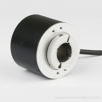
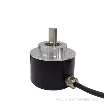
Model: 3808
Packaging: SMD
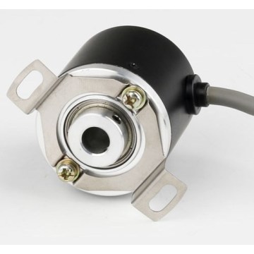
Installation form: shaft sleeve type
Axonia: Synchronous flange type
Rotary encoder: 38mm
Transportation packaging: cardboard boxes
Specification: CE ROHS
Origin: Jilin
Installation form: shaft sleeve type
Brand: China Ruihua
Axonia: Synchronous flange type
Rotary encoder: 38mm
Trademark: cnruihua
Transportation packaging: cardboard boxes
Specification: CE ROHS
Origin: Wenzhou
S38 series rotary encoder
1. Professional manufacture for rotary encoder
2. Good quality
3. Sold well in the oversea market
4. Have CE approve
1. Professional manufacture for rotary encoder, founded in 2005.
2. Good quality
3. Sold well in the oversea market
4. Have CE approved
Incremental rotary encoder, optical rotary encoder, rotary position encoder
Package 40 PCS for one carton, one carton gross weight 7.5kg
2000 Pairs Sells per Month
5 pairs MOQ
48-72 hours delivery after received money
ELECTRICAL SPEC
output circuit
open collector NPN output
voltage output
push pull output
line driver output
supply voltage
5-24
5-24
5± 0.25 5-24
5± 0.25 5-24
current consumption
≤ 80mA
≤ 80mA
≤ 80mA
≤ 150mA
load current
40mA
40mA
40mA
60mA
single high level
min Vcc*70%
min Vcc-2.5V
min Vcc-1.5V
min 3.4V
single low level
Max 0.4V
Max 0.4V
Max0.8V
Max 0.4V
rising time Tr
Max 1us
Max 1us
Max 1us
Max 200ns
declining time Tr
Max 1us
Max 1us
Max 1us
Max 200ns
response frequency
300kHz
300kHz
300kHz
300kHz
MECHANICAL SPEC
number of pulses
starting torque without sealing
Max load permitted on shaft
shock resistance
vibration proof
2500
≤ 0.05Nm
radial 50N, Axial 20N
50G /11ms
10G 10-2000Hz
rotational inertia
Working temperature
Storage temperature
Protection class
Weight
4x10 -8 kgm 2
- 30 ~ 85 C
- 35 ~ 95 C
IP65
100g
About Payment
We provided Trade Assurance service
We also accept payment by T/T; Western Union, ESCROW, Paypal, Money gram
We Provide OEM Services
We can do OEM for your brand (print your logo ). And we can make product according to your design .
The processing method ,the size ,the quality etc ,will all follow your requirement .
We do OEM for a lot of the world's leading brands ,we have rich experience in production. We have molds in varieties ,and we have strict products quality control system.
We have a strong R&D team, to develop new products according to the sample you provided.
2023-12-09
The rotary incremental encoder outputs a pulse when it is rotated, and its position is known by the counting device. When the encoder is not moving or power is off, the internal memory of the counting device is used to remember the position. In this way, when the power is off, the encoder can't have any movement. When the caller works, the encoder can not interrupt and lose the pulse during the output pulse. Otherwise, the zero point of the counting device will shift, and this bias The amount of shift is unknown, and only the wrong production result can be known.
The solution is to increase the reference point, and the encoder corrects the reference position into the memory position of the counting device every time the encoder passes the reference point. Before the reference point, the accuracy of the position cannot be guaranteed. For this reason, in the industrial control, there are methods such as finding a reference point for each operation, and starting to change the zero.
For example, the positioning of the printer scanner is the incremental encoder principle. Every time we turn it on, we can hear a bang, it is looking for the reference zero, and then it works.
This method is more troublesome for some industrial control projects, and even does not allow booting to change to zero (you must know the exact position after booting), so there is an absolute encoder.
Absolute rotary photoelectric encoders have been widely used in angle, length measurement and positioning control in various industrial systems because of their absolute uniqueness, anti-interference and no need for power-down memory.
There are many scribe lines on the absolute encoder optical disc. Each line is followed by 2 lines, 4 lines, 8 lines and 16 lines. Orchestration, so that at each position of the encoder, by reading the pass and dark of each reticle, a set of unique binary codes from the zeroth power of 2 to the n-1 power of 2 is obtained (Gray Code), this is called an n-bit absolute encoder. Such an encoder is determined by the mechanical position of the code wheel and is immune to power outages and interference.
Absolute encoder uniqueness of each position determined by the mechanical position, it does not need to remember, no need to find a reference point, and do not have to count all the time, when you need to know the position, when to read its position. In this way, the anti-jamming characteristics of the encoder and the reliability of the data are greatly improved.
Since absolute encoders are significantly superior to incremental encoders in positioning, they have been increasingly used in industrial positioning. Due to its high precision, the absolute encoder has a large number of output bits. If parallel output is still used, each output signal must ensure that the connection is good, and it is isolated for more complicated working conditions, and the number of connecting cable cores is large. It brings a lot of inconvenience and reduces reliability. Therefore, the absolute encoder is a serial output or a bus type output in the multi-digit output type. The most commonly used serial output of the absolute encoder produced in Germany is SSI (synchronous string). Line output).
Rotating a single-turn absolute encoder from a single-turn absolute encoder to a multi-turn absolute encoder to measure each line of the optical encoder in rotation to obtain a unique code. When the rotation exceeds 360 degrees, the code is returned. To the origin, this does not conform to the principle of absolute coding. Such an encoder can only be used for measurements within a range of 360 degrees, called a single-turn absolute encoder.
If you want to measure the range of rotation over 360 degrees, you need to use a multi-turn absolute encoder.
The encoder manufacturer uses the principle of the watch gear mechanism. When the center code wheel rotates, another set of code wheels (or sets of gears, multiple sets of code disks) is driven by the gear, and the number of turns is increased on the basis of the single-turn coding. Encoding to expand the measuring range of the encoder, such an absolute encoder is called a multi-turn absolute encoder, which is also determined by mechanical position determination, and each position code is unique and does not need to be memorized.
Another advantage of the multi-turn encoder is that due to the large measurement range, the actual use is often more affluent, so that it is not necessary to find a zero point during installation, and an intermediate position is used as a starting point, which greatly simplifies the difficulty of installation and debugging.
Multi-turn absolute encoders have obvious advantages in length positioning and have been increasingly used in industrial positioning.
2023-12-05
In the information technology era, security products have attracted more and more attention. In network monitoring systems, encoders are the bridge between monitoring storage and transmission. Rotary encoder is a common encoder, commonly used in monitoring video transmission equipment, speed measuring generators and other security products, used to measure the speed and with the PWM technology can achieve fast speed device, photoelectric rotary encoder through photoelectric conversion The output shaft angular displacement, angular velocity and other mechanical quantities can be converted into corresponding electrical pulses for digital output (REP).
Rotary encoders are divided into single output and dual output. The technical parameters mainly include the number of pulses per revolution (tens to several thousand), and the supply voltage. Single output means that the output of the rotary encoder is a set of pulses, while the dual-output rotary encoder outputs two sets of pulses with 90-degree phase difference between A and B. Through these two sets of pulses, not only the rotation speed but also the rotation can be determined. The direction.
Rotary encoder installation techniques are also very particular about, such as improper operation is likely to lay hidden security risks, the following we understand the installation of rotary encoder related issues.
Do not apply direct impact to the shaft during installation
The connection of the encoder shaft to the machine should use a flexible connector. When installing the connector on the shaft, do not press hard. Even if the connector is used, special attention must be paid to the fact that the shaft may be loaded with a larger load than the allowable load due to poor installation, or the core removal phenomenon may occur.
The bearing life depends on the conditions of use and is particularly affected by the bearing load. If the bearing load is smaller than the specified load, the bearing life can be greatly extended.
Do not disassemble the rotary encoder. Doing so will impair oil and drip resistance. Anti-drip products should not be immersed in water or oil for a long time, and should be wiped clean when there is water or oil on the surface.
Vibration can cause false impulses
The vibration added to the rotary encoder is often the cause of false pulses. Therefore, pay attention to the installation site and installation site. The greater the number of pulses per revolution, the narrower the slot spacing of the rotating slot disc, the more susceptible to vibration. When rotating or stopping at a low speed, the vibration applied to the shaft or the body shakes the rotating groove disc and false pulses may occur.
Wiring connection pay full attention to <br> <br> Incorrect wiring may damage the internal circuit, it should give full attention to the wiring:
1. The wiring should be performed with the power OFF. When the power is turned on, if the output line contacts the power supply, the output circuit may be damaged.
2. If the wiring is incorrect, the internal circuit may be damaged, so pay attention to the polarity of the power supply when wiring.
3. If the wiring is conducted in parallel with the high-voltage line or the power line, it may be induced to malfunction and be damaged. Therefore, separate the wiring.
4. When extending the wire, it should be less than 10m. Moreover, due to the distribution capacity of the electric wire, the rise and fall time of the waveform will be longer. When there is a problem, the waveform is shaped using a Schmidt circuit or the like.
5. To avoid induced noise, etc., try to use the shortest distance wiring. When inputting to an integrated circuit, special attention needs to be paid.
6. When the wire is extended, the rise and fall times of the waveform are prolonged due to the influence of the conductor resistance and the line capacitance, and interference (crosstalk) between the signals is likely to occur. Therefore, a wire with a small resistance and low capacitance between the wires (twisted pair) is used. Shielded wire).
For HTL encoders with a symmetrical negative signal output, the signal transmission distance can reach 300 meters.
2023-12-04


 Ms. Nicole
